Snapmaker Enclosure Door Reversal#
I recently moved my Snapmaker 2.0 A350T printer to another part of my home. The official enclosure has a solid panel on the left side, a large door on the right, and a smaller door on the front. These panels are only designed to be installed in one specific order and orientation.
In this post I describe the steps I took to swap the solid panel and large door as well as “flip” the front panel so it opens on the opposite side. There are a few minor drawbacks to this modification but the solutions I came up with neutralizes them. These workarounds are also non-desctructive so I can restore my enclosure back to its original design.
Drawbacks#
Foot fixtures: The bottom rails have extra screw holes and indentations so that the foot fixtures can be installed precisely. The top rails lack these indentations and screw holes.
Solution: If you have bought the emergency stop button you may have four spare T-nuts and M4x8 screws you can use (if not you can buy extra M4 2020 T-nuts or you can just drill and tap new threaded holes in the rails). You should also measure the distance between the indentation and the end of the bottom rails and mark them on the top rails with a marker.
Touchscreen: Since we’re rotating everything 180 degrees the touchscreen cutout on the front door will be at the top instead of the bottom. We’ll be fixing this by flipping the panel but this will place the foam strips facing out instead of in.
Solution: Buy some 10 mm wide by 3 mm thick self-adhesive weather stripping (or cut yours to size).
Top panel: The bottom side of the enclosure doesn’t have as many screw holes as the top. Only the two narrow sides of the top panel will have holes that align.
Solution: You can drill additional holes on the plexiglass top panel or using more T-nuts but I ended up just relying on the four screws to hold the top panel in place, so this was a non-issue for me.
Steps#
Remove all plexiglass panels and doors.
Remove the rear top (with the converter hub) and rear bottom 24 BEAM A350-4 rails.
Measure the offsets of the foot fixture indentations on the bottom rails (my enclosure measured 123 mm offset).
Facing front to back flip the entire enclosure 180 degrees (e.g. top is now on the bottom).
Relocate the LED strips from the bottom to the top rails (the tiny screws aren’t necessary).
Flip the hall sensor (little black box on a vertical rail) 180 degrees so you can run the cable along the top.
For the foot fixtures insert two M4 2020 T-nuts into each bottom rail.
Mark on the now-bottom rails the foot fixture offsets.
Reinstall the rear rails, keeping the one with the converter hub at the top.
Install the doors. Flip the small-door panel with the touchscreen cutout and apply the self-adhesive weather stripping on the flipped panel.
Pictures#
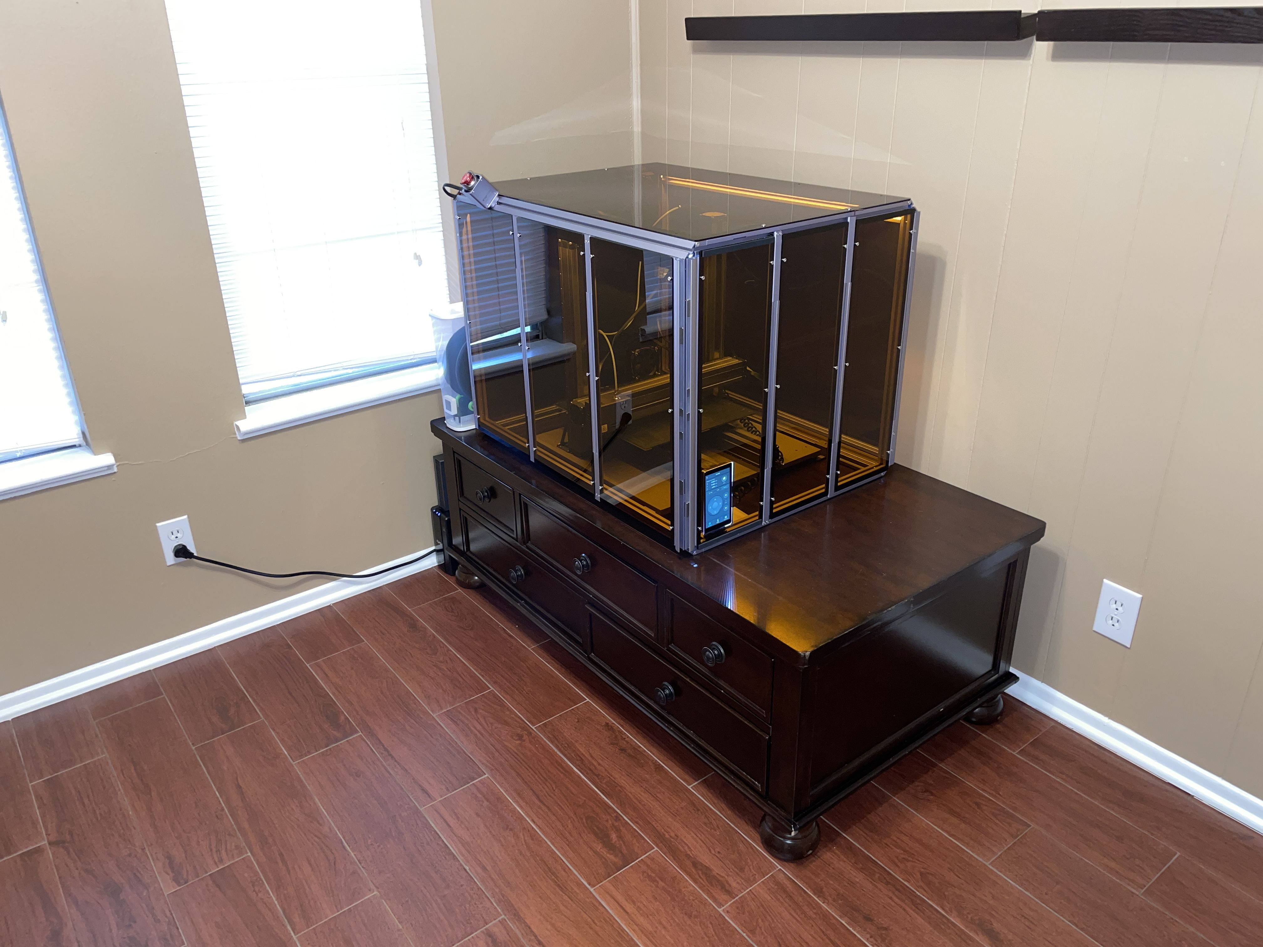
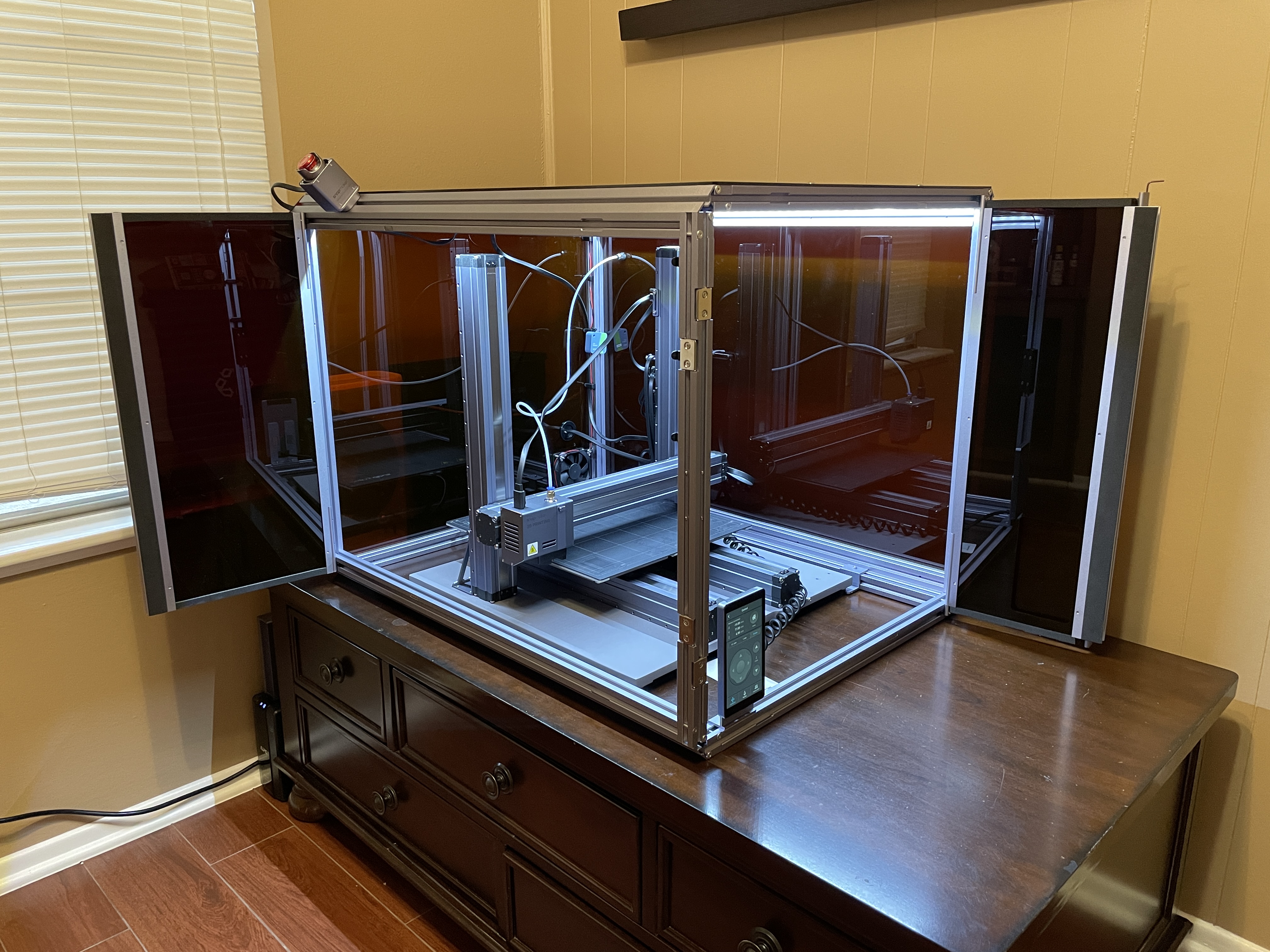
Finished project. |
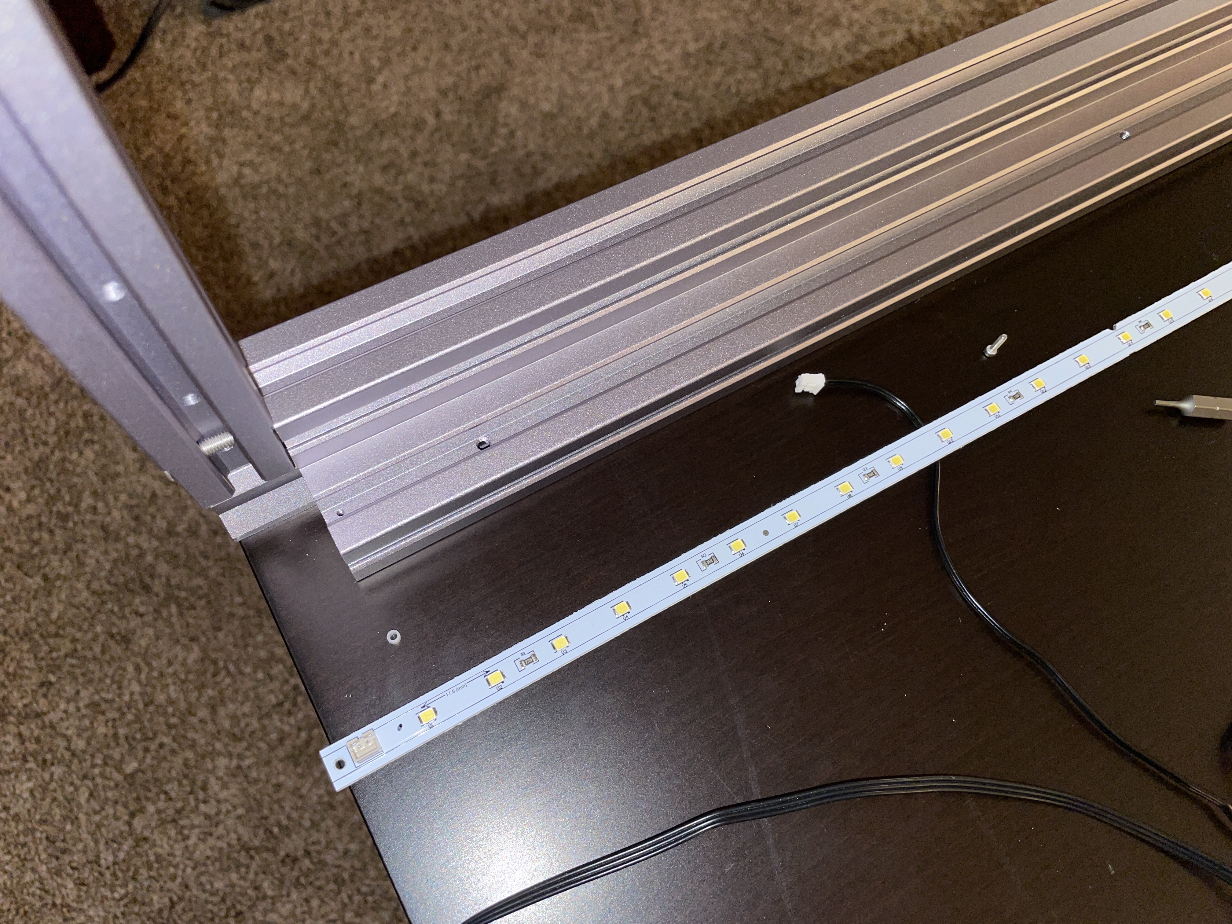
Removed the LED strips from the now-bottom rails to relocate them back to the top of the enclosure. |
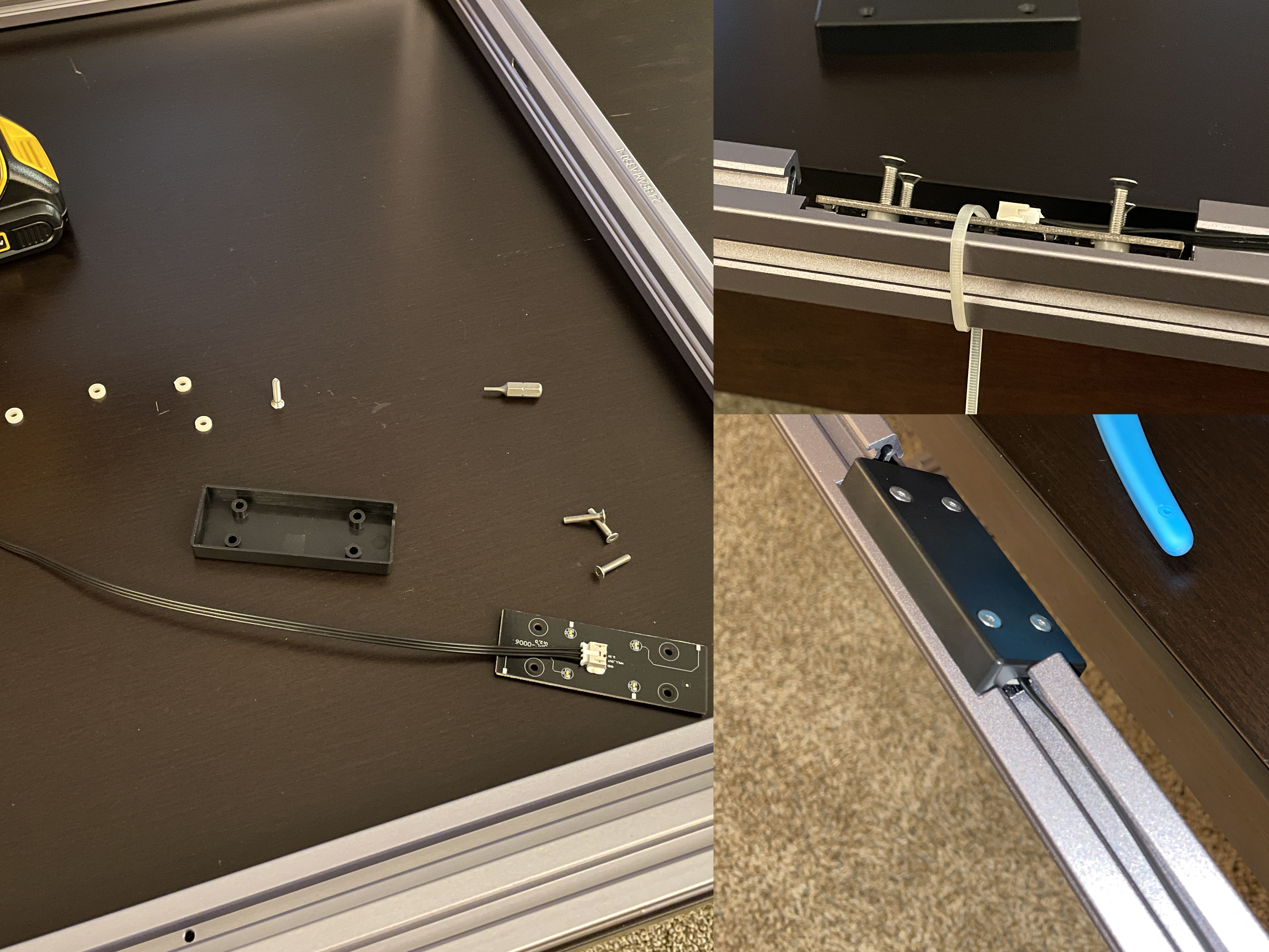
Flip the hall/door sensor. I used a zip tie to help keep the plastic washers in place. The sensor actually has bright white LEDs that light up when it detects when the two doors are closed. |
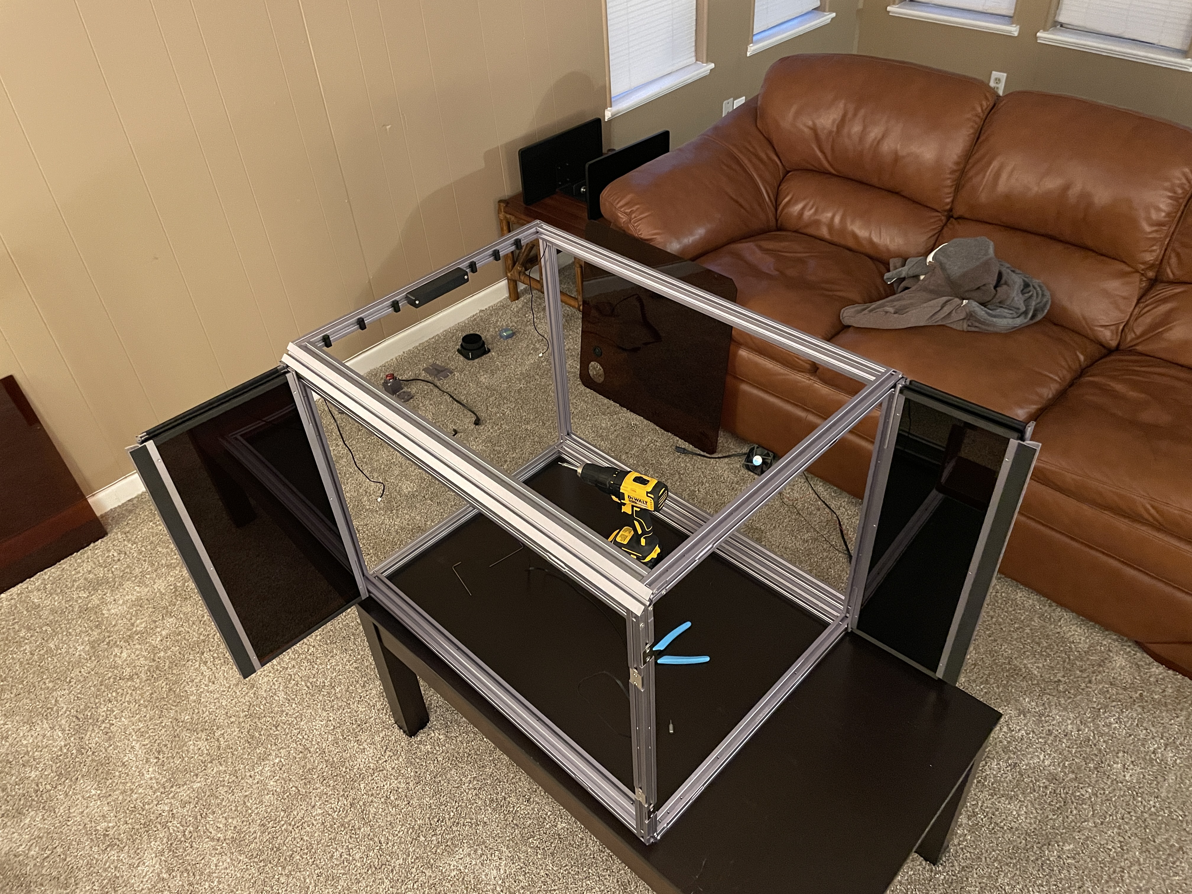
Half way through I put the doors on to verify they fit and close properly. The magnets are aligned just fine. |
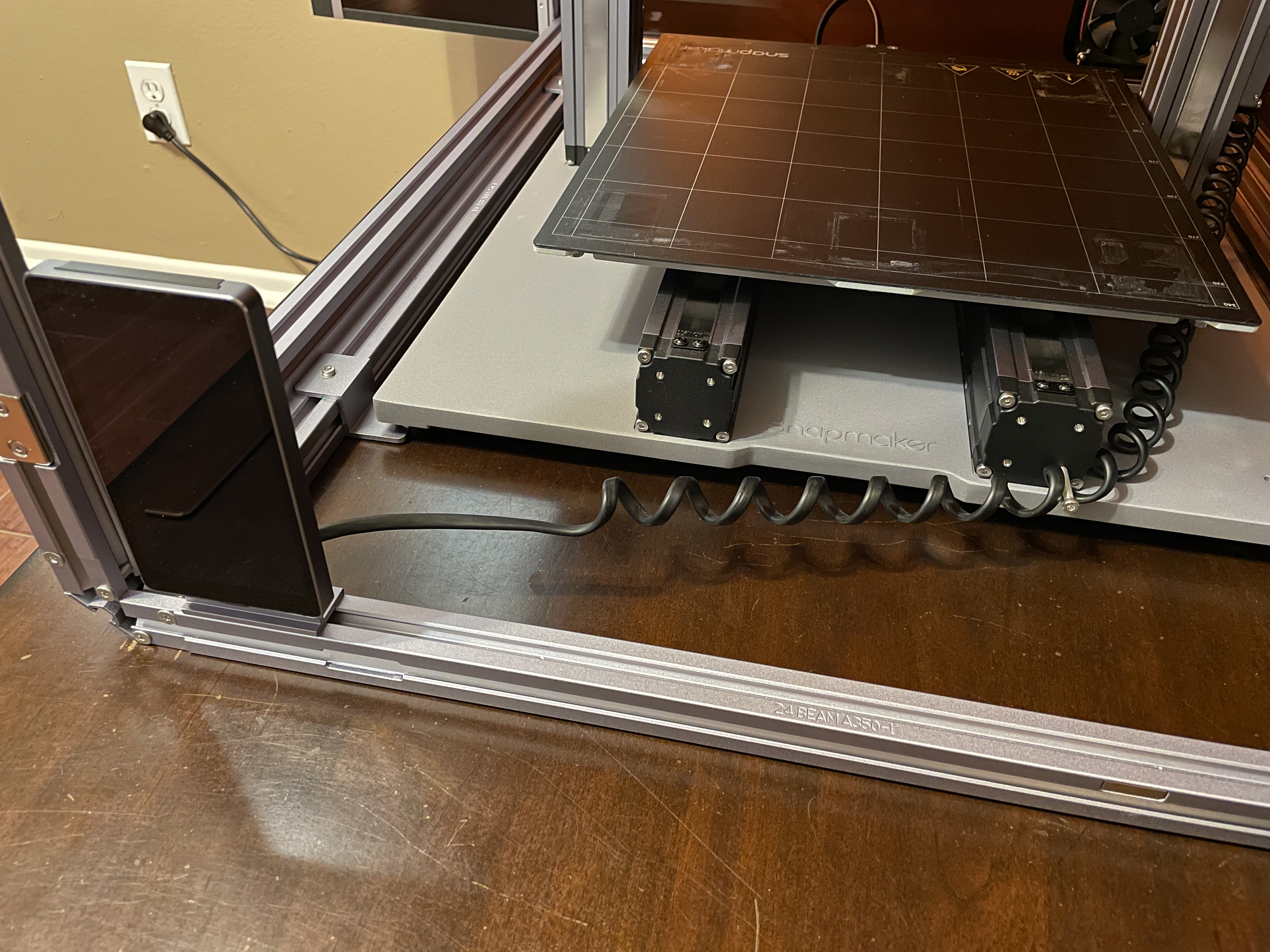
Mark where the foot fixtures will go and use T-nuts to fasten them in place. |
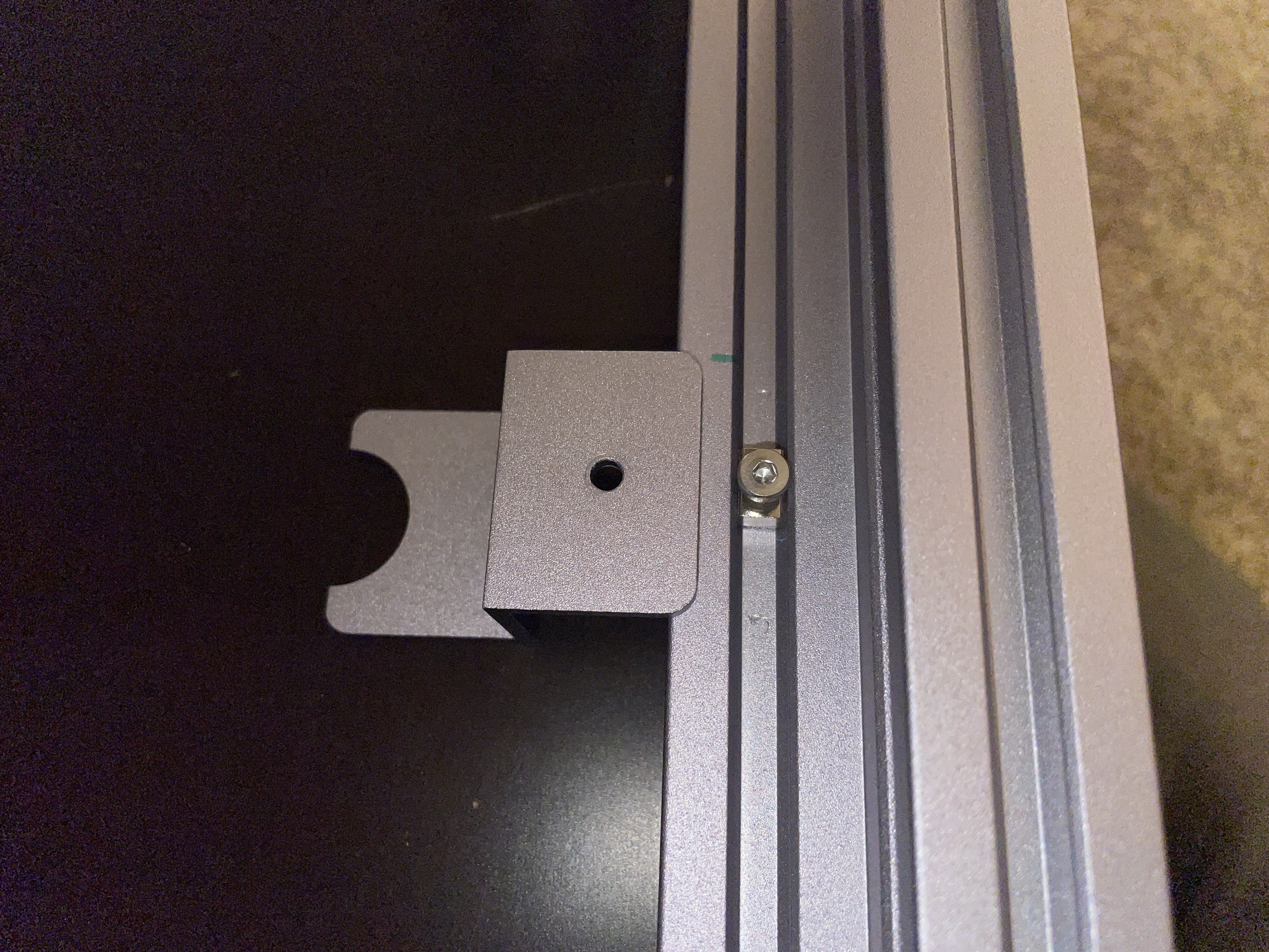
The touchscreen cord is long enough to reach its new location. I used a spare screw to ensure it won’t ride up and touch the hot platform or get pinched by the moving platform. |
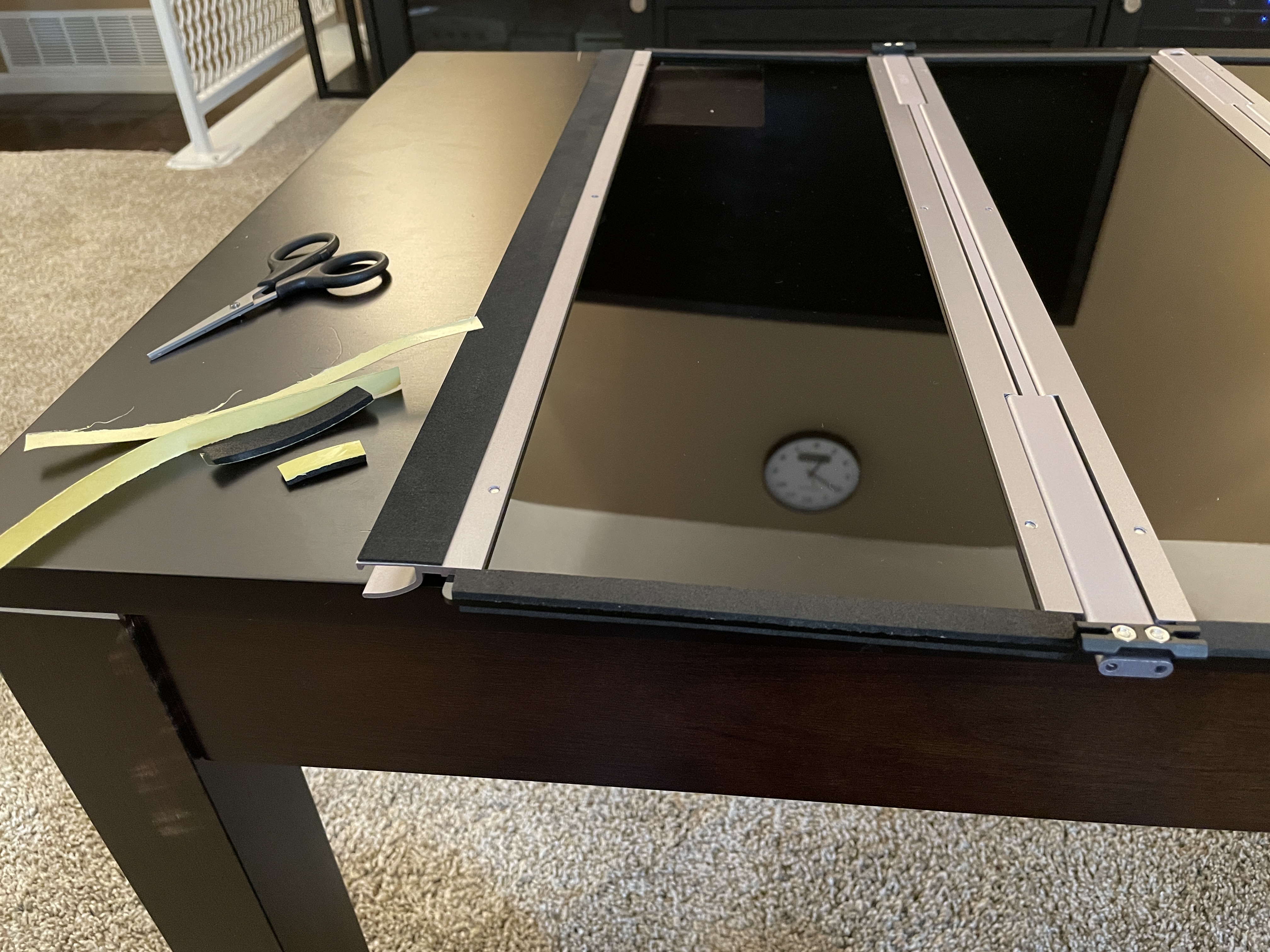
Installed some additional weather stripping after flipping this enclosure panel with the touchscreen cutout. |
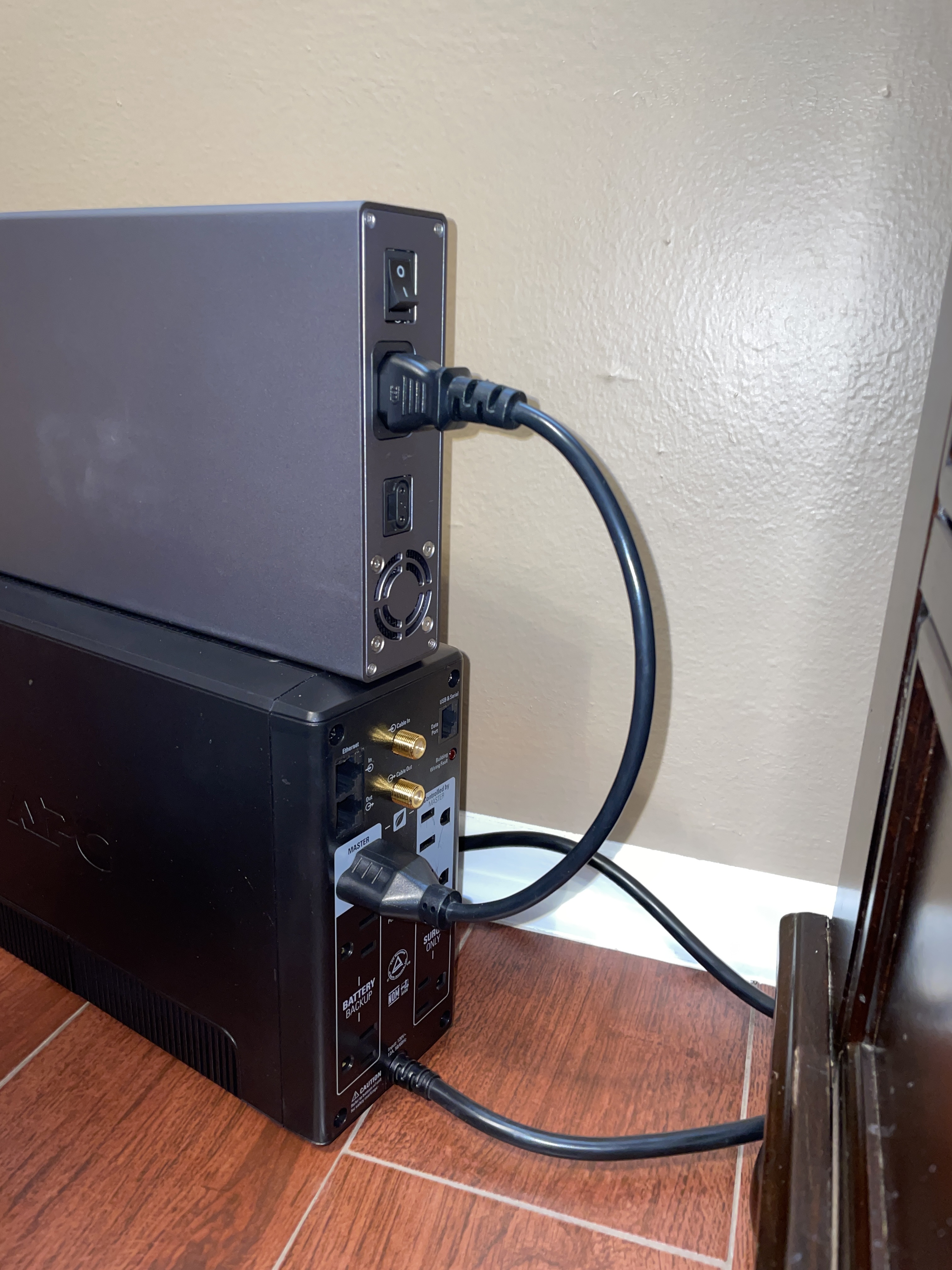
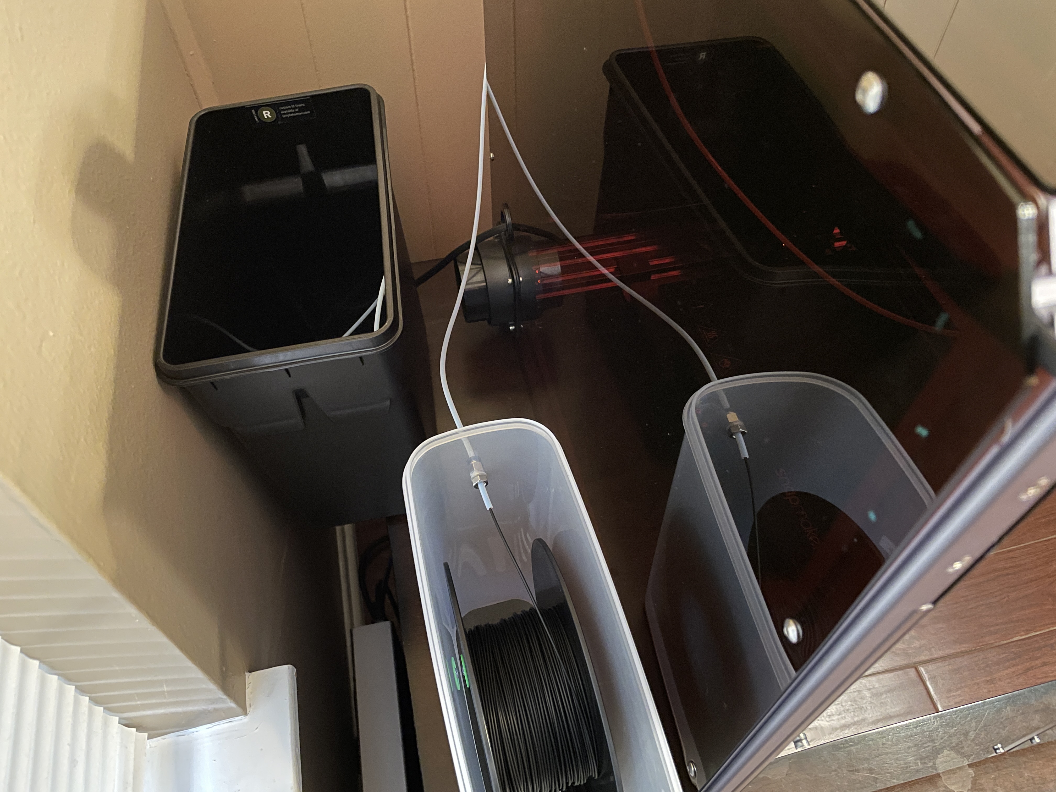
Unrelated: for my new coffee table setup I’m moving the power supply to be on top of the UPS and not take up table space. |
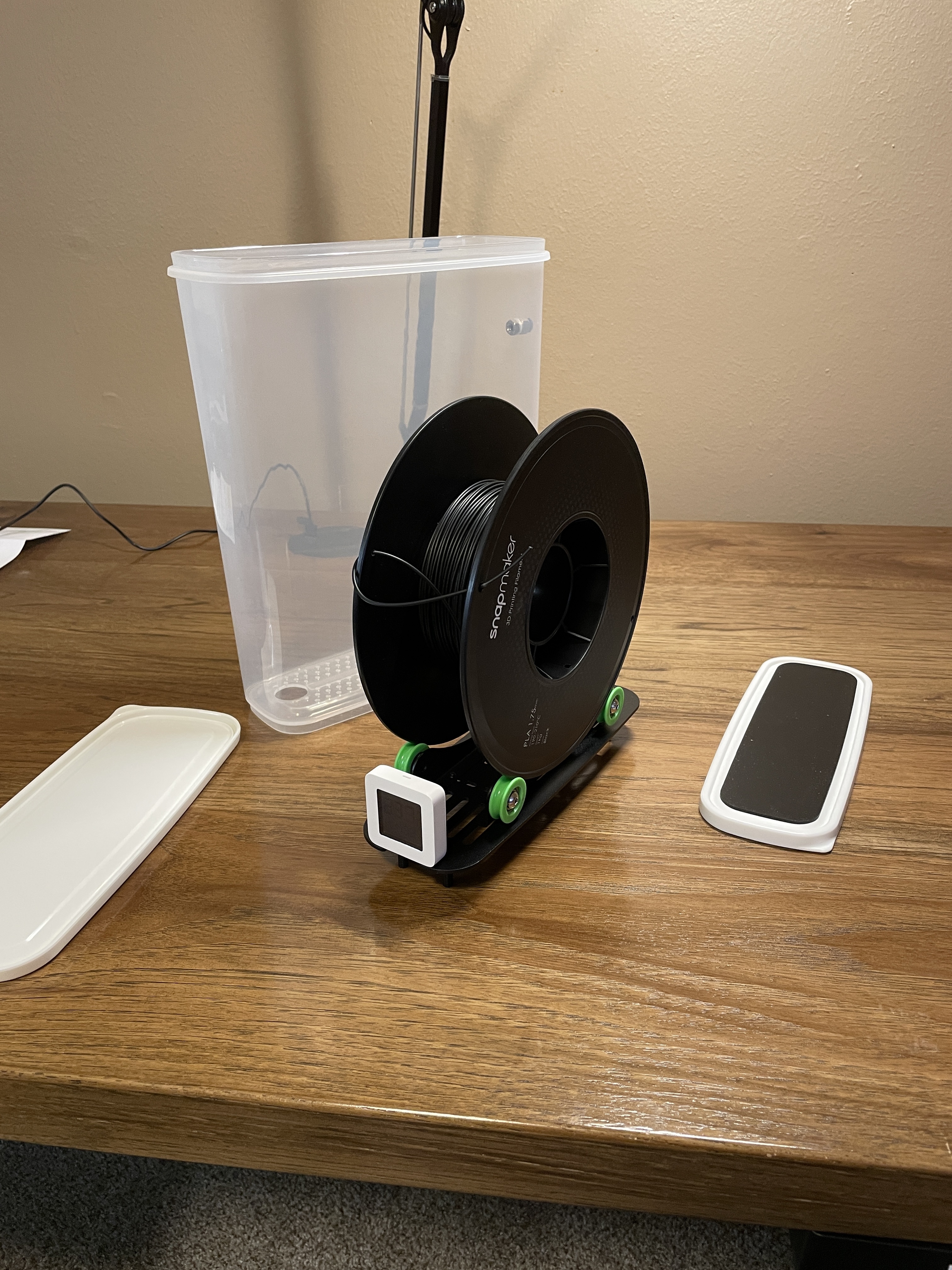
I bought a filament dry box from Amazon instead of relocating the spool holder which would have required cutting or drilling into the enclosure panels. This works for me because I already use a PTFE/Teflon tube with my printer. |
Done! |
Teflon tube routing: dry box |
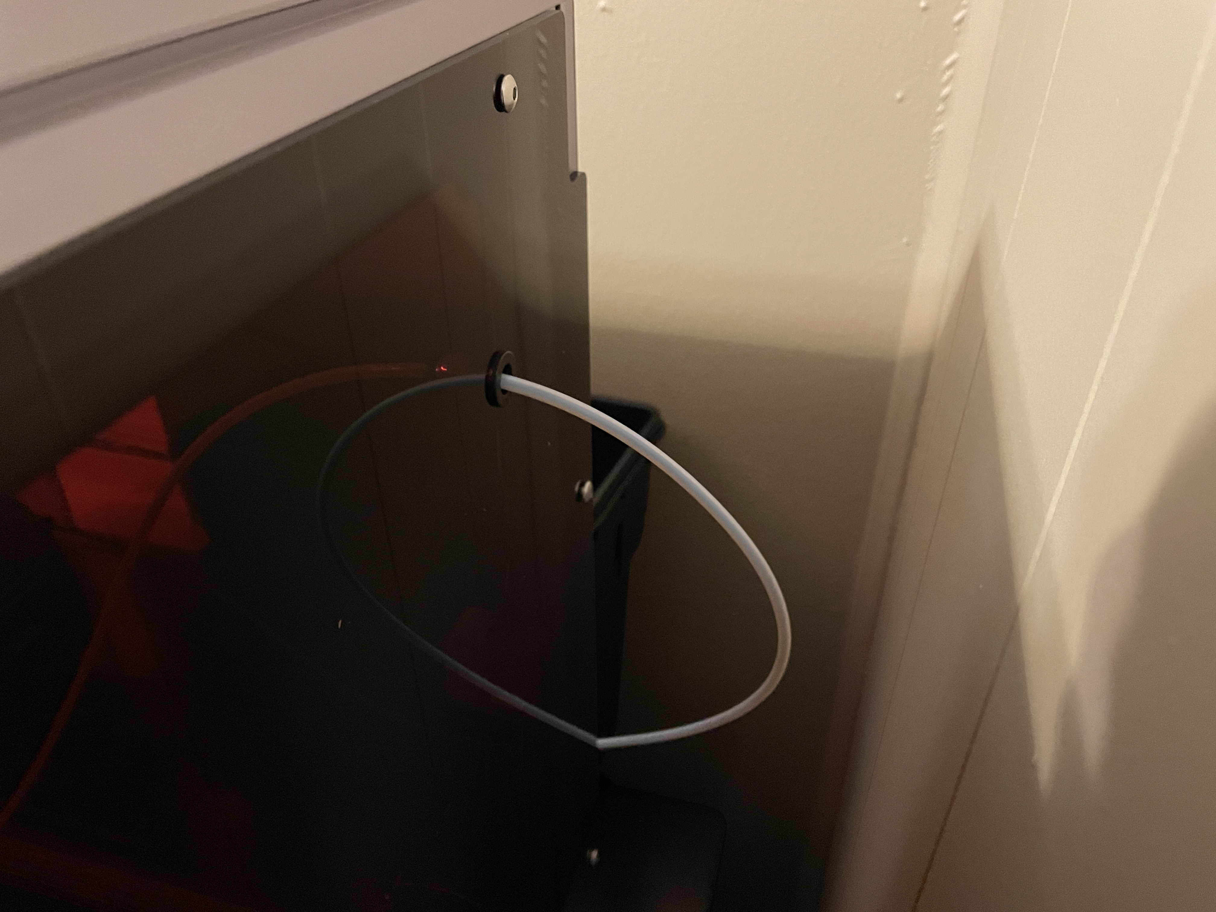
Teflon tube routing: enclosure through-hole |
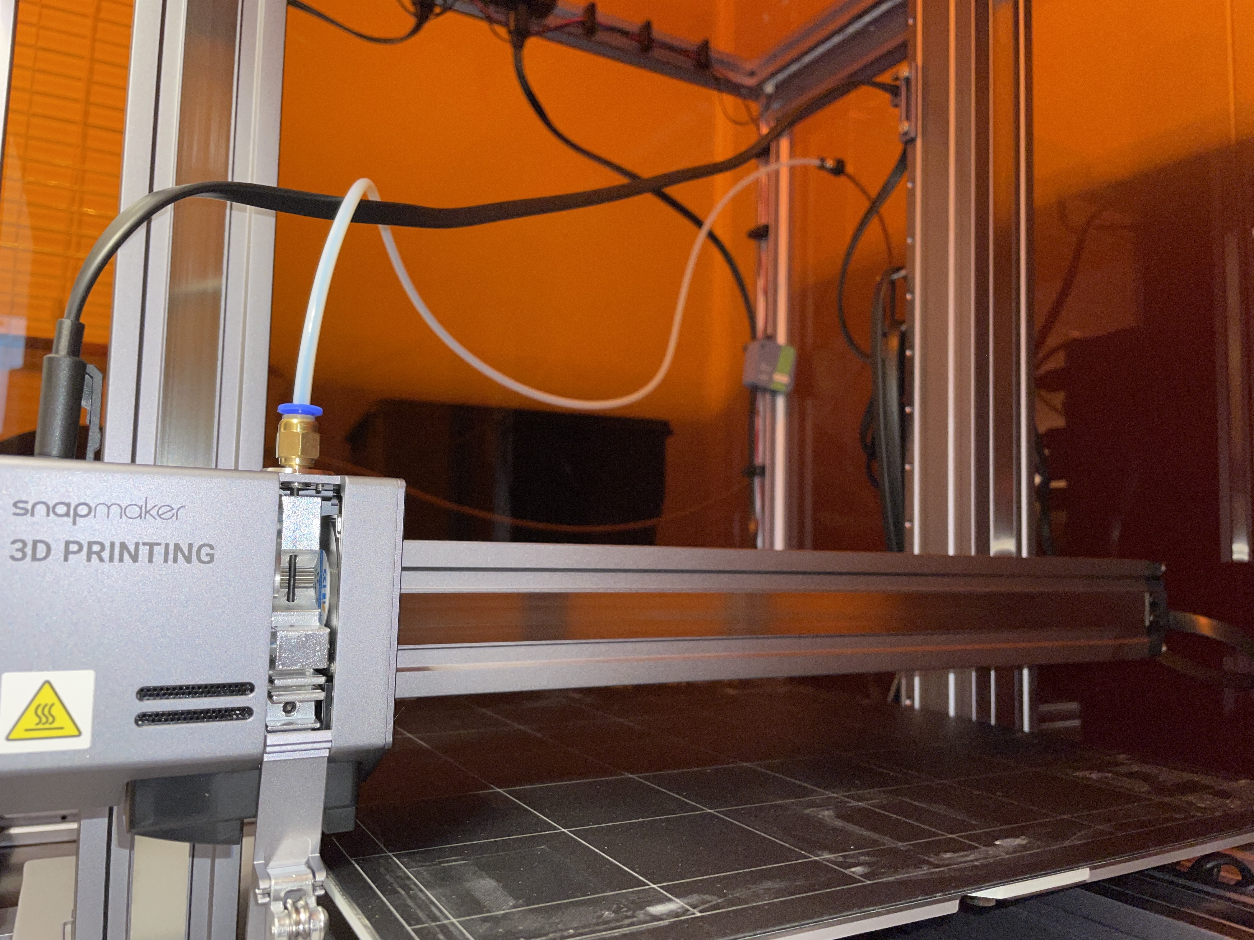
Teflon tube routing: print head |
Comments
comments powered by Disqus